
1) Why these three ideas matter
Electrical machines (motors, generators, transformers, actuators) all boil down to three physical pillars:
- Rotating magnetic field (RMF) — how we create a moving magnetic pattern that pulls conductors (or rotors) around.
- Flux path — how magnetic flux
 actually travels through iron, air gaps, and windings, and how reluctance shapes it.
 - Electromagnetic force/torque — how current-carrying conductors in a magnetic field experience force
 and convert electrical power to mechanical power (or the reverse).
Below, we’ll build these from first principles, give you compact but rigorous equations, and then walk through six worked problems (2 beginner, 2 intermediate, 2 advanced). Every formula and special symbol is wrapped for WP QuickLaTeX compatibility.
2) Rotating magnetic field (RMF)
In a balanced three‑phase stator, each phase current is sinusoidal, time‑shifted by  , and spatially distributed by . The vector (space‑phasor) sum of these stator mmfs forms a constant‑magnitude magnetic field that rotates at synchronous speed.
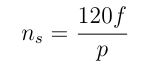
The synchronous mechanical speed in rpm is

where
 = supply frequency (Hz)
 = number of poles
The corresponding electrical angular speed (rad/s) is

In induction machines, the rotor lags the RMF, creating slip:

with  the rotor mechanical speed (rpm). Slip governs rotor frequency, torque, and losses.
3) Flux path & magnetic circuits
Magnetics often parallels DC circuits:
- Flux: (Wb)
- MMF:
 (A‑turn)
 - Reluctance:
 (A‑turn/Wb)
Thus,

Air gaps dominate reluctance because  for air, while iron has
  . Consequently, tiny geometry changes in the air gap (e.g., eccentricity, saliency) strongly affect flux and torque.
For transformers (no mechanical rotation), Faraday’s law rules:

Sinusoidal steady‑state gives the familiar per‑turn volts:

4) Electromagnetic force and torque
The Lorentz force on a conductor segment of length  carrying current
  in magnetic flux density
  :
:

In many machine models, average torque can be compactly expressed as proportional to flux and current. A classic DC torque law:

More generally (for any electromechanical device where energy is stored magnetically), torque can be derived from co‑energy:

If inductance depends on position  , e.g.,

then with constant current  ,
,

This underpins torque production in reluctance motors, stepper motors, and synchronous machines with saliency.
For synchronous machines, the well‑known power‑angle relation (neglecting resistance) is

with  the stator terminal voltage magnitude,
  the internal emf magnitude,
  synchronous reactance,
  the torque (load) angle, and
  the synchronous electrical rad/s.
5) How these appear in real machines
- Induction motors: RMF induces rotor currents at frequency
 ; electromagnetic torque peaks near moderate slip; at
  (synchronous), torque → 0.
 - Synchronous machines: Rotor locks to the RMF (
 ); torque controlled by and field excitation; stability tied to the slope of the power‑angle curve.
 - Reluctance & stepper motors: Torque from position‑dependent inductance; shaped salient poles create a strong
 .
. - Transformers: No mechanical torque, but the same flux‑linkage principles determine induced voltages, leakage reactance, and core losses.
6) Six worked problems (with full solutions)
Beginner Level (2)
B1. Synchronous speed
A three‑phase machine has  poles and operates from
  . Find the synchronous speed
  in rpm.
Solution

B2. Flux in a simple core
A magnetic core (uniform cross‑section) has  turns, carries
  , mean path length
  , cross‑sectional area
  , and relative permeability
  . Compute flux .
Solution
Reluctance

MMF

Flux

Intermediate Level (2)
I1. Slip and rotor frequency
A 4‑pole induction motor is fed at  and runs at
  . Find slip
  and rotor current frequency
  .
.
Solution

Rotor frequency

I2. Lorentz force on a bar
A straight conductor of length  carries current
  and lies perpendicular to a uniform field
  . Compute the force magnitude.
Solution

Advanced Level (2)
A1. Torque from a position‑dependent inductance
A doubly‑salient machine has
with  ,
,  . It is excited by a constant current
  . Derive
  and evaluate it at
  .
.
Solution
Co‑energy for a current‑controlled device:

Torque:


Thus,

Convert  :
:

At ,  ,
,  :
:

The negative sign indicates the torque tends to move the rotor toward decreasing co‑energy gradient (stable alignment position).
A2. Synchronous machine power‑angle torque
A round‑rotor synchronous generator has  ,
,  , and
, and  . It operates at
  , , . Compute electrical air‑gap power
  and torque
  .
.
Solution
Use phase quantities. Convert L‑L to phase (star):

Electrical power (neglecting resistance):

Compute:

Multiply by  :
:

Synchronous electrical rad/s (mechanical speed is  ; electrical rad/s equals mechanical rad/s times pole pairs
  , but we can more directly compute mechanical and then divide power):
Mechanical synchronous speed
Mechanical rad/s

Torque

7) Key takeaways
- Three‑phase windings naturally synthesize a rotating field; pole count and frequency set .
- Flux prefers low‑reluctance paths; the air gap dominates magnetic design.
- Electromagnetic torque can be obtained from Lorentz force or co‑energy; both are consistent and invaluable, especially for salient/reluctance machines.
- Practical machine equations (slip torque curves, power‑angle characteristics) are all direct consequences of these fundamentals.
Leave a Reply