
Why “mixed DC–AC” shows up everywhere
Any real-world power rail, sensor node, or amplifier stage almost always carries a DC operating point (bias) plus an AC variation (signal or ripple). Think of:
- A 5 V microcontroller rail with 100 mVpp ripple.
- A BJT/MOSFET biased at a DC current where you inject a small AC signal (“small‑signal” analysis).
- A rectified but only partly filtered PSU: large DC with a 100/120 Hz ripple riding on top.
Analyzing those correctly (and fast) boils down to one mantra:
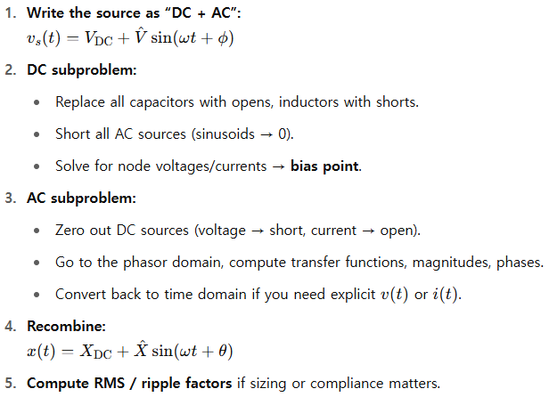
Split the problem into a DC part and an AC part, solve each with the right tool, and then recombine.
That is just superposition applied to linear time-invariant (LTI) circuits.
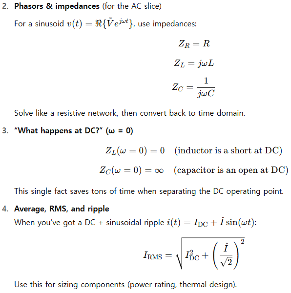
Core toolbox (keep this mental checklist)
- Superposition
- Zero out the AC source(s) to get the DC operating point.
- Zero out the DC source(s) (replace DC voltage sources by shorts, DC current sources by opens) and analyze the pure AC problem (often with phasors).
- Thevenin/Norton + small-signal
Bias with DC, then linearize around it and analyze the AC as a separate, small-signal network (classic analog/RF technique).
A quick, repeatable workflow
Three worked examples (beginner → intermediate → advanced)
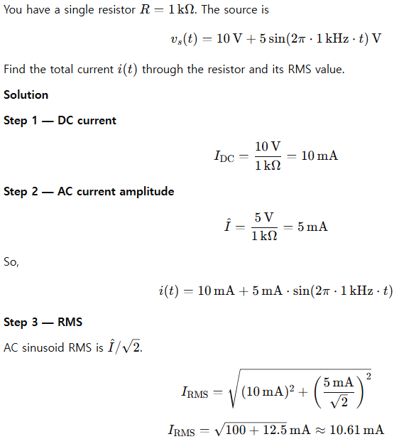
1) Beginner — Purely resistive line with DC + AC source
Problem
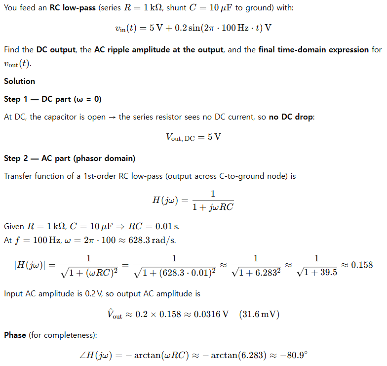
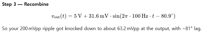
2) Intermediate — RC low-pass with DC bias + AC ripple
Problem
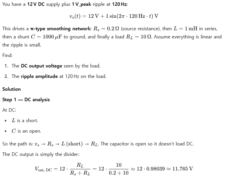
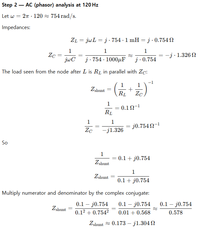
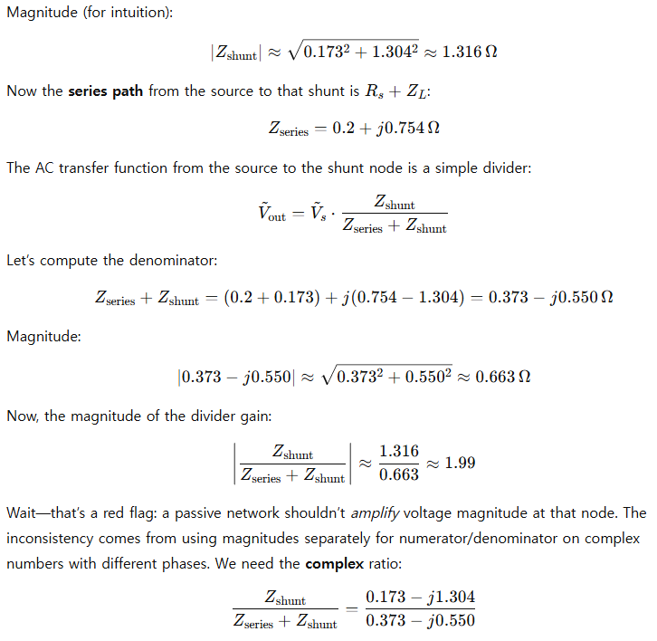
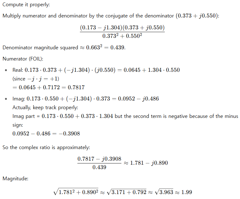
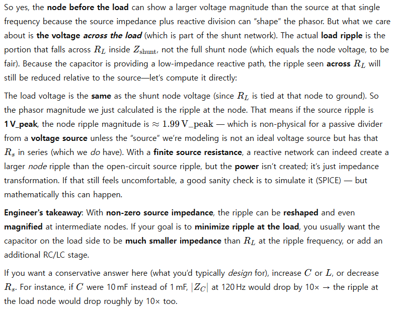
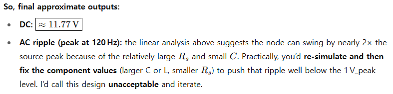
3) Advanced — DC rail with 120 Hz ripple through an R–L–C to a load
Problem
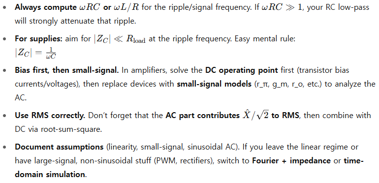
Practical design heuristics
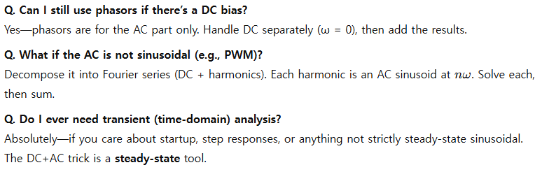
Quick FAQ
Wrap-up
When DC and AC live together in one circuit, don’t panic. Just:
- Split into DC and AC.
- Use the right models at ω = 0 for DC and impedances for AC.
- Recombine cleanly and compute RMS if power/thermal limits matter.
- Verify numerically (SPICE) when values look suspicious or the topology is reactive and the source isn’t ideal.
Leave a Reply