
Frequency Response and Resonance in Series and Parallel RLC Circuits
When we talk about AC circuits, one of the most fascinating topics is how the circuit responds to different frequencies. This is where frequency response and resonance come into play. In this post, we’ll go through how series and parallel RLC circuits behave at different frequencies, how resonance happens, and what it means practically. We’ll also look at three solved problems—from beginner to advanced—to help you get hands-on with the concepts.
📌 What Is Frequency Response?
Frequency response refers to how the output of a circuit changes as the input signal frequency varies. In RLC circuits, the interaction between resistance (R), inductance (L), and capacitance (C) causes the circuit to react differently depending on the frequency of the input voltage or current.
For example:
- Inductors resist high-frequency signals.
- Capacitors resist low-frequency signals.
So depending on the frequency, the voltage or current in the circuit might be amplified, attenuated, or stay the same.
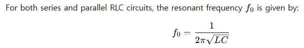
📡 Resonance in RLC Circuits
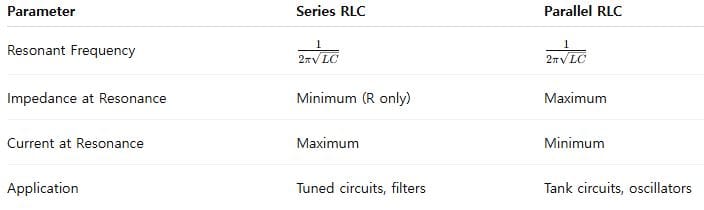
Resonance occurs when the inductive and capacitive reactances cancel each other out. This happens at a particular frequency known as the resonant frequency.
At resonance:
- In a series RLC circuit, the total impedance is minimum, and the current is maximum.
- In a parallel RLC circuit, the total impedance is maximum, and the current drawn from the source is minimum.
🔁 Series RLC Circuit: Frequency Response
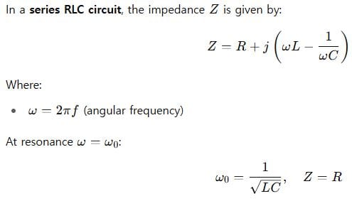
That means the inductive and capacitive reactances cancel each other, and only resistance remains.
The circuit behaves like a pure resistor at this point.
🔁 Parallel RLC Circuit: Frequency Response
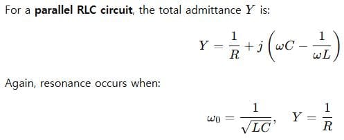
So the circuit draws minimum current from the source and behaves like an open circuit to AC at that resonant frequency.
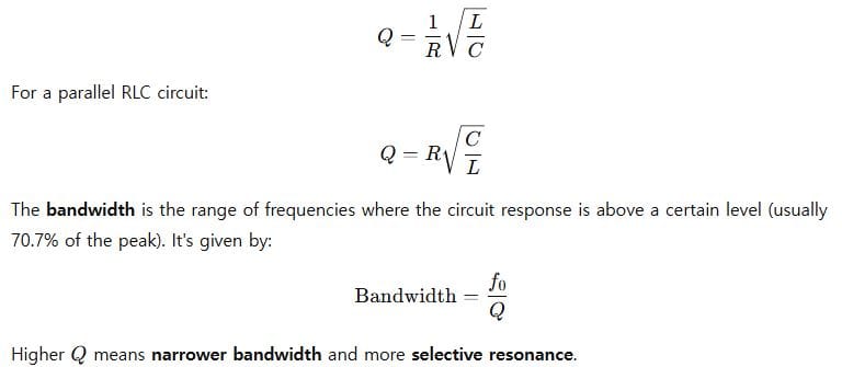
🔎 Quality Factor and Bandwidth
The Quality Factor (Q) tells us how sharp or selective the resonance is.
For a series RLC circuit:
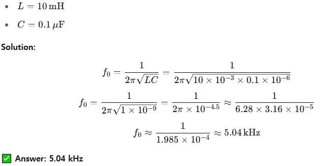
🔰 Example 1 (Beginner)
Problem:
Find the resonant frequency of a series RLC circuit with:
⚙️ Example 2 (Intermediate)
Problem:
A parallel RLC circuit has the following:
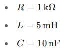
Calculate:
- Resonant frequency
- Quality factor
- Bandwidth
Solution:
(1) Resonant Frequency:
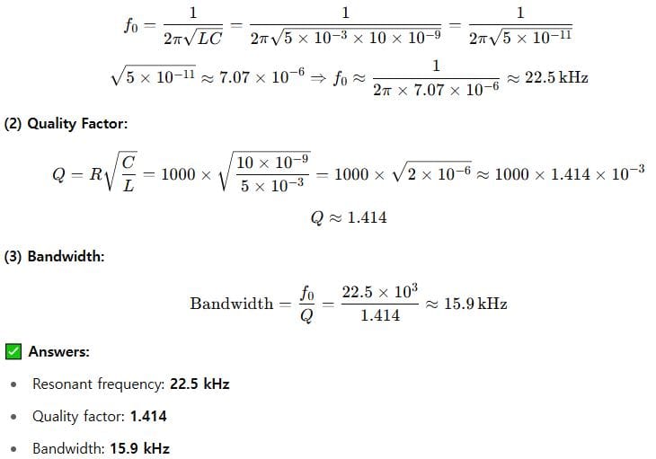
🧠 Example 3 (Advanced)
Problem:
🧩 Summary
📌 Final Thoughts
Resonance in RLC circuits isn’t just a textbook topic—it’s central to everything from radio tuning to signal processing. Understanding how frequency response works in both series and parallel configurations will help you design better circuits and interpret system behaviors more effectively.
Let me know in the comments if you’d like a calculator tool for these formulas or want to see a simulation-based explanation next time.
Leave a Reply