
RL and RC Transient Circuits Explained in a Friendly Way
When you first hear the term “transient response,” it might sound like something straight out of a science fiction movie. But in the world of electronics, it’s a very real and important concept. In this post, we’ll explore first-order circuits, specifically RL and RC circuits, and focus on their transient behavior—how voltage and current change over time when something suddenly switches.
We’ll break it down step by step, include math where needed (don’t worry, nothing too crazy), and work through three full example problems, ranging from beginner to advanced.
What Is a Transient Response?
In simple terms, the transient response is what happens to the voltage and current in a circuit immediately after a change, like when you flip a switch or apply a new voltage source. This response is temporary—it lasts until the circuit settles into a new steady state.
Transient responses usually happen when you have components like resistors (R) and either:
- Inductors (L) → RL circuits
- Capacitors (C) → RC circuits
The RL Circuit: Basics
Let’s start with the RL circuit.
A simple series RL circuit consists of a resistor RRR and an inductor LLL connected to a voltage source. When the voltage source is applied, the inductor resists sudden changes in current.
The current in the circuit is given by:
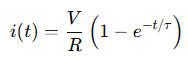
Where:
The RC Circuit: Basics
Now, for the RC circuit, the capacitor resists changes in voltage.
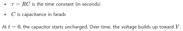
For a series RC circuit with a resistor R and a capacitor C, the voltage across the capacitor when charging is:
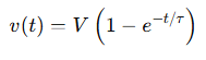
Where:
Why the Time Constant Matters
The time constant τ\tauτ gives us an idea of how quickly the circuit responds.
- After 1τ, the response reaches about 63% of its final value.
- After 5τ, the circuit is almost fully settled (over 99%).
So, larger inductance or capacitance = slower response. Larger resistance also slows things down.
🔹 Beginner Example – RC Charging Circuit
Problem:
A 10V battery is connected to a 1kΩ resistor and a 100μF capacitor in series. Find the voltage across the capacitor after 0.1 seconds.
Given:
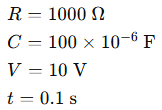
Step 1: Find the time constant τ
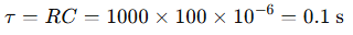
Step 2: Use the voltage formula:
Answer: The voltage across the capacitor is approximately 6.32V after 0.1 seconds.
🔹 Intermediate Example – RL Current Growth
Problem:
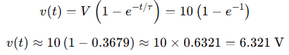
An RL circuit with a 50Ω resistor and a 0.2H inductor is connected to a 12V battery. How much current flows after 0.05 seconds?
Given:
Step 1: Find time constant τ:
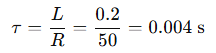
Step 2: Calculate current:
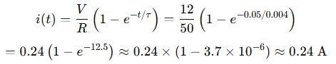
Answer: Almost the full current flows—0.24A—after just 0.05 seconds.
🔹 Advanced Example – RC Discharging with Initial Voltage
Problem:
A 4.7μF capacitor is initially charged to 9V. It discharges through a 2.2kΩ resistor. What’s the voltage after 5 milliseconds?
Given:
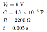
Step 1: Time constant:

Step 2: Voltage formula for discharge:
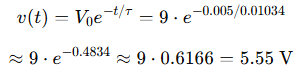
Answer: The capacitor voltage is approximately 5.55V after 5ms.
Real-World Relevance
These circuits aren’t just for textbooks. You’ll find RL and RC circuits in:
- Power supplies
- Audio equipment
- Timing circuits
- Sensor filtering
- Microcontroller debouncing
- Motor drive circuits
Understanding the transient response helps you design, troubleshoot, and optimize circuits for real applications.
Conclusion
In a nutshell, RL and RC circuits teach us how energy is stored and released over time. Whether it’s the current building up through an inductor or voltage climbing across a capacitor, these first-order systems are foundational to all of electronics.
With practice, these equations won’t feel intimidating—they’ll feel like your toolbox. Get comfortable with the time constant, remember the basic exponential behavior, and always check units!
If you’re working with microcontrollers, analog electronics, or even simple hobby projects, knowing how to predict and control transient behavior can make the difference between a circuit that works and one that frustrates you.
Leave a Reply