
Mesh Current Method: A Friendly Guide to Loop Analysis
If you’ve ever looked at a messy circuit and wondered how to make sense of it, you’re not alone. That’s exactly why engineers love the Mesh Current Method, also called Loop Analysis. It’s a systematic way to analyze planar circuits by focusing on the loops instead of individual nodes. Let’s break it down in a conversational and practical way—no formal tone, just straight talk and real examples.
What Is the Mesh Current Method?
At its core, the Mesh Current Method is a technique for solving circuits using Kirchhoff’s Voltage Law (KVL). Instead of dealing with all the currents going in and out of each node (as in the Node Voltage Method), we create “meshes” — the smallest possible loops in the circuit — and assign a current to each one.
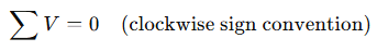
We then apply KVL to each loop, which states:
The algebraic sum of all voltages in a loop equals zero.
This allows us to form a set of equations and solve for the unknown mesh currents.
When Should You Use Mesh Analysis?
Mesh analysis is particularly effective for:
- Planar circuits (no wires crossing in 3D)
- Circuits with many series elements
- Situations where you’re more interested in current than voltage
It becomes a bit messier with current sources or non-planar configurations, but don’t worry—we’ll cover how to handle those later on.
Step-by-Step: How to Apply the Mesh Current Method
- Label All Meshes
Assign a clockwise mesh current (e.g., I₁, I₂, I₃…) to each loop. - Apply KVL to Each Mesh
Write an equation for each loop summing all the voltage drops and sources. - Account for Shared Elements
If a component lies between two meshes, the voltage drop depends on the difference of the two mesh currents. - Solve the System of Equations
Use substitution, elimination, or matrix methods.
Key Formulas
When you hit a resistor shared by two loops:
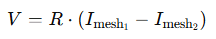
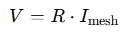
When it’s a unique resistor in one mesh:
When you include a voltage source:
🔰 Example 1: Basic Mesh Analysis (Beginner)
Circuit Description
- One voltage source (10V)
- Two resistors (2Ω and 3Ω) in a single loop
10V → [2Ω] → [3Ω] → back to source
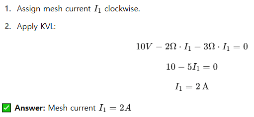
Step-by-step:
- Assign mesh current clockwise.
- Apply KVL:
10V → [2Ω] → [3Ω] → back to source
Step-by-step:
⚙️ Example 2: Two Meshes with Shared Resistor (Intermediate)
Circuit Description
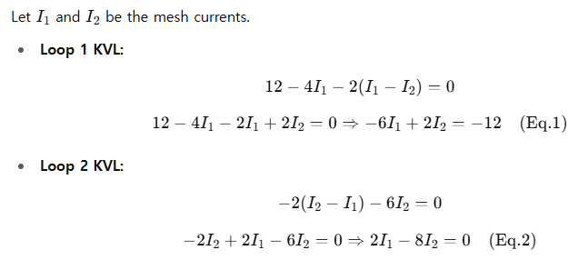
- Mesh 1: 12V source, 4Ω resistor
- Mesh 2: 6Ω resistor
- Shared resistor: 2Ω between two meshes
Loop 1: 12V → [4Ω] → [2Ω] shared
Loop 2: [2Ω] shared → [6Ω]
Step-by-step:
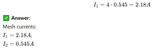
Solving Eq.1 and Eq.2:
From Eq.2:

Sub into Eq.1:

Then:
🧠 Example 3: Mesh Analysis with Current Source (Advanced)
Circuit Description
- Loop 1: 5Ω, 2Ω, and 10V source
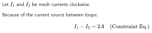
- Loop 2: 3Ω, 1Ω, and a 2A current source between the loops
The 2A current source is between the two loops → Supermesh needed.
Step-by-step:
Now create a supermesh (Loop around both meshes, avoiding the current source):
Supermesh KVL:

Use constraint equation:
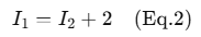
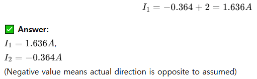
Sub Eq.2 into Eq.1:

Then:
Tips and Tricks
- Always draw the circuit and label meshes clearly.
- Use clockwise mesh current as a habit—it’s just a convention but helps avoid confusion.
- If you get a negative current, it just means your assumed direction was opposite. No big deal.
- Watch out for dependent sources in advanced problems—they follow the same method but require extra attention to controlling variables.
Final Thoughts
The Mesh Current Method is a must-have tool in every electrical engineer’s toolkit. It takes a little practice, but once you get the hang of setting up and solving those equations, even the messiest circuits become manageable. Keep practicing with more examples, and this method will soon feel like second nature.
Need to move to 3D circuits or ones with complex interconnections? That’s when you explore Node Voltage Method or simulation tools—but for planar DC analysis, Mesh is king.
Kirchhoff’s Voltage Law made Easy: Advanced Level Guide
Leave a Reply